Home >> Retaining Rings >> Automated Assembly for Axial Rings
Automated Assembly for Axial Rings
Automated Assembly is used in the manufacturing process as a cost
reduction tool that additionally achieves increased production rate and
added quality through repeatability.
The same holds true for automated assembly of retaining rings. Parts can
be assembled fast, reducing costs without sacrificing quality. Properly
designed installation equipment shuttles the ring into the groove without
disruption and guards against permanent set (overstretching/over
compressing of ring) to ensure a tight fit.
Design Considerations
Feed equipment should be designed to work with rings meeting standard specifications. Most critical is to design equipment that can accommodate the helix and pitch limitations for the type of ring you are using. If the equipment is sensitive to any of these factors, it will require special processing that will add to your costs.
Design guidelines include:
1. Consider use of a tapered mandrel for external retaining rings and a tapered housing for internal retaining rings (see below). It is not recommended to pick up and transfer rings by the lug holes.
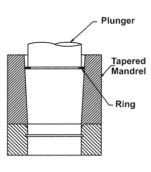
Internal
Use tapered housing to compress ring and install in groove in housing. (Note: angle of inclination of taper should be 3-5 degrees)
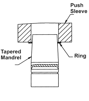
External
Use tapered mandrel to expand ring and install in groove on shaft. (Note: angle of inclination of taper should be 3-5 degrees)
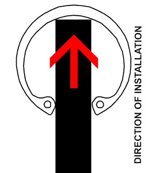
Figure A
This is the preferred way to transfer feed an internal ring into a tapered housing by inserting the mechanism between the lugs. (Note: Finger thickness should be 80% of the minimum ring thickness)
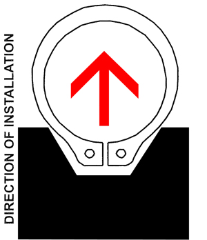
Figure B
This is the preferred way to transfer feed an external ring onto a tapered mandrel by using a slide with a complimentary cut out for the lugs. (Note: Finger thickness should be 80% of the minimum ring thickness)
3. Feed finger thickness should be sized per ring: .80% of the ring minimum thickness. (For example: If ring thickness is .025” +/-.002, feed finger should be .018” thick–.023 x 80%).4. Limit shuttle distance to a minimum from feed mandrel to installation on assembly.
5. Do not incorporate extension sleeves to tapered mandrel/tapered housing. This may exceed the expansion/compression limits of the ring causing it to fail. (Note: extension sleeves are typically used to guard against scratching/marring the finish of the shaft or housing. If this is a concern, please consult Daemar® Technical Sales).
6. Incorporate complementary chamfers to the assembly and installation mandrels.


