Home >> Blog >> Design Equipment to Promote Better Seal Performance
Design Equipment to Promote Better Seal Performance
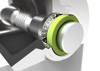
For a seal to optimally operate requires the appropriate design of the two components that the seal interacts with – the Bore and the Shaft. The Bore should have an adequate lead in chamfer and proper tolerancing to allow a proper press fit of the seals outer casing when installed, this will prevent leakage between the seal and bore and it will eliminate any rotating or movement of the seal during operation. Manufacturing the shaft with proper lead in chamfer, appropriate diameter and surface finish will increase seal performance and extend the operating life of the seal. Minimizing shaft movement (run-out) and misalignment will increase sealing performance and limit seal lip wear.
Design of the Bore
Proper application Bore Design assures proper sealing performance. Using the following guide will ensure the best possible sealing environment.
- Bore Material – Steel and cast iron are typically used for bore housings as they provide a good surface for accepting both metal and rubber O.D. seals
- Bore Hardness- There is no recommended Rockwell hardness for the bore. However, the bore should be of sufficient hardness to withstand the seal’s O.D.
- Bore Finish – The bore finish should be 0.8 to 1.6 μm Ra for metal O.D. seals and should be 2.5 to 5.0 μm Ra for rubber O.D. seals
- Bore Lead-in Chamfer – The lead corner, or entering edge of the bore should be chamfered and free of burrs
- Bore Tolerance – refer to our Bore Tolerance Tables
Design of the Shaft
Proper application Shaft Design assures proper sealing performance. Using the following guide will ensure the best possible sealing environment.
- Shaft Material – Seals perform best on medium to high carbon steel (SAE 1035, 1045) or stainless steel.
- Shaft Hardness – The shaft must be hardened to Rockwell C45 minimum.
- Shaft Finish – We recommend the shaft to be machined to a surface roughness of 0.20 to 0.8 µm Ra (8 to 32 µin Ra). This shaft finish can be best obtained by plunge grinding.
- Shaft Lead-in Chamfer – The end of the shaft must be chamfered, corners must be rounded, free from burrs and sharp edges to protect seals from damage during assembly.
- Shaft Tolerance – refer to our Shaft Tolerance Tables
- Shaft Eccentricity – There are two types of shaft eccentricities that affect the seal’s performance. They are Shaft to Bore Misalignment and Dynamic Run-Out.
- Shaft-to-bore misalignment is the distance that the centre of shaft rotation is from the centre of the bore. This situation causes excess sealing lip wear, and poor contact between the lip and shaft on the opposite side
- Dynamic run-out is twice the distance the centre of shaft is displaced from the actual centre of rotation. Meaning that the shaft is not rotating around its centre, causing the lip to flex in and out in order to maintain shaft contact. In the extreme the lip will not be able to provide the required seal.
To learn about selecting the correct seal for your operating environment please refer to our article Extending Seal Life Starts with Proper Selection. For recommendations on how best to install shaft seals and to prevent seal damage during installation review our information on appropriate seal installation procedures.
