
Home >> Slide >> Fiber-Lube Bushings >> CJ/FCJ Fiber-Lube Bearing Wear
Bearing Wear
Design consideration when selecting the correct fiber-lube bushing for your application. Factors that affect bearing wear include: load capacity, lubrication, operating conditions (PV factor, shaft finish, temperature…).
The equilibrium wear rate depends on a number of factors including loads, speeds, shaft hardness, and shaft surface finish. Under laboratory conditions, radial wear is approximately proportional to both sliding distance and load. The wear rate is often reported as a factor K. This relationship can be expressed as follows:
The following table shows the actual measured wear factor for a number of conditions of oscillation and rotation. These values were obtained using Rc 50 shafts with a surface finish of 16 Ra(.4 μm).
The wear factor would increase if the shaft material was softer or the surface finish rougher.
The performance using the softer shafts was significantly lower, especially at the higher load condition.
While performance is lower, it is adequate for many less demanding applications.
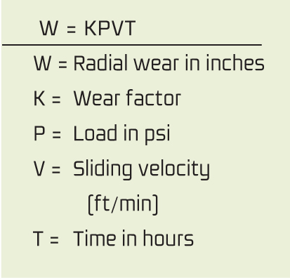
Using wear factors, the radial wear of a CJ bearing can be estimated by calculating W and adding .001” (.025 mm) for break-in wear. The liner can sustain .015-.020” (.38 mm-.51 mm) wear and still operate normally. Bearings having an inside diameter of over 2-1/2” have a thicker liner capable of sustaining .025” to .030” (.64mm – .76mm) wear. Surface finish affects wear rate as shown in (See Figure B, to the left) Field experience has shown that hard chrome plating gives excellent wear performance and protects the shaft from corrosion. Softer coatings such as cadmium and zinc will not stand up in service and quickly wear off.
Load Capacity
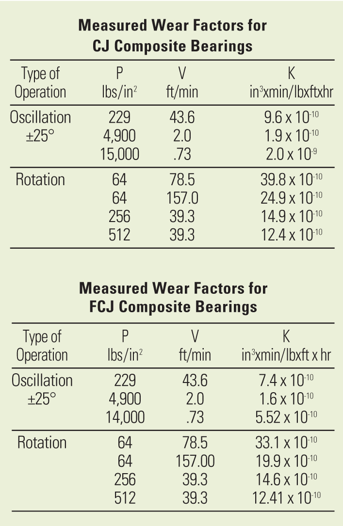
Normal application of load will cause a simple elastic deflection of the CJ bearing along with some permanent set. The set is primarily due to compaction of the synthetic fiber/PTFE liner. We do not typically recommend subjecting the bearings to over 35,000 psi (241 MPa) load. In common with other materials, fiberglass/epoxy composites can undergo fatigue after repeated application of stress. Fatigue has not been a limiting factor in the use of the CJ bearing. In fact, laboratory tests have shown that in many cases the bearing is more fatigue-resistant than the shaft. Laboratory tests show that the bearings fail by a gradual crushing action rather than a rapid catastrophic failure. This is consistent with typical composite behavior in which stress is supported by many fibers. If one fiber breaks, the load is redistributed among the others. Breakage of the entire structure will not occur until a large number of the individual fibers are broken. CJ composite bearings can easily withstand over 35,000 psi (241 MPa) static load or 20,000 psi (140 MPa) dynamic load with a great deal of reliability.
In many cases, higher loading can be tolerated if the design and conditions of service are discussed fully with Daemar bearing specialist.
Length to diameter ratio is also an important design consideration. Test results from the laboratory and the field have shown that the optimum performance can be attained by specifying a length to inside diameter ratio (L/D) ranging from .5 to 2. When the L/D ratio of less than .5 is used, it is possible to create highly stressed areas at the corner of the bearing and cracking will occur at this location prematurely. If the L/D ratio is over 2, with any amount of shaft misalignment, cross corner jamming will occur and unit stresses can exceed the 15,000 psi (103 MPa) safe dynamic limit or the 35,000 psi (241 MPa) static limit of the bearings. Bearings built with the proper L/D ratio will accept misalignment and shock load without premature failure.
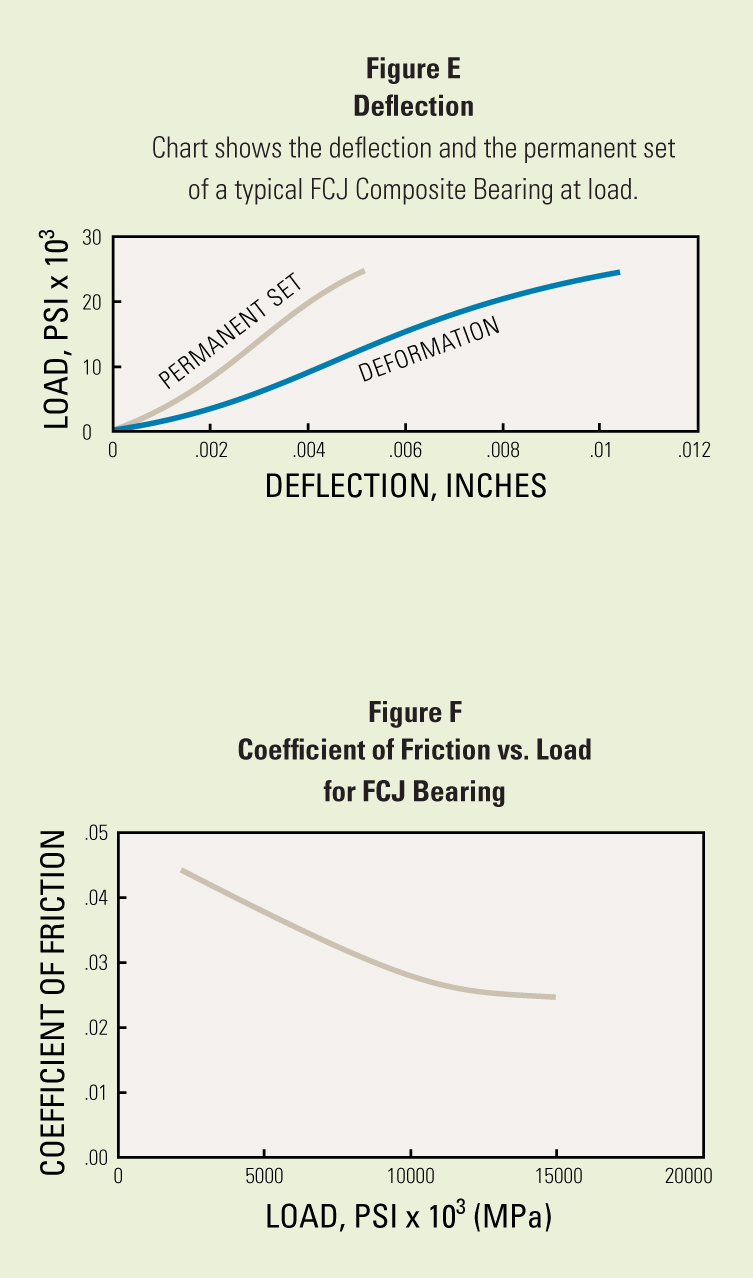
The coefficient of friction of a synthetic fiber/PTFE lined composite journal bearing running against a hardened Rc 50 steel shaft with a 16 Ra (.4 μm) surface, or less, varies from .02 to .25 depending on the load, the relative sliding velocity, and the bearing surface temperature. Generally, the coefficient of friction decreases with increasing load (See Figure D,on left side).
This information indicates that if the lowest coefficient of friction is desired, the smallest bearing capable of sustaining the load should be used, and that the bearings are capable of performing best under peak operating conditions when temperatures and loads may be higher.
Lubrication
The synthetic fiber/PTFE fabric wear surface of the CJ bearing is a self-contained boundary lubrication system; however, the addition of conventional lubricants often improves the overall performance of the CJ bearing. “Lubricant” is a very general term, and it is often said that any liquid will act as a lubricant. To some extent, this is true if hydrodynamic conditions are established, and the surfaces have minimal contact. The composite bearing, in earth moving equipment, operates generally in a state of boundary lubrication. Hydrocarbon oils are advantageous and can produce tenfold reductions in wear rates. Liquid lubricants can carry away heat and reduce the coefficient of friction. Greases can be used for lubrication, to prevent corrosion, and keep contamination out of the journal. In oscillating motion, the synthetic fiber/PTFE liner acts as a true boundary lubricant when the direction of motion changes and the lubrication film collapses. In rotation, with oil lubrication, the wear rate of the CJ composite has been found equal to sintered or cast bronze bearings. Fluorocarbon oils and greases should be avoided because they have been found to soften the synthetic fibers and greatly increase the rate of wear. It is possible to add lubrication holes to the CJ bearing, but grooves are impractical. The abrasion resistance of the synthetic fibers makes groove fabrication difficult and costly.
Thermal Properties
The operating temperature range for CJ bearings is -320°F to +300°F (-195°C to +149°C). The bearing has been heat stabilized at a temperature above 300°F (149°C) and very little dimensional change will occur in the bearing during operation. In the free state, the coefficient of expansion of the CJ bearing in the radial direction is approximately 7 x 10⁻⁶ in/in/°F. When press fit into a housing, the CJ bearing assumes the coefficient of expansion of the housing material, as long as the press fit is maintained, and thus the elastic modulus of the bearing is maintained, because the elastic modulus of the bearing is lower than the elastic modulus of most metals.
The CJ composite is a thermal insulator and when heat is generated from running friction, the bearing wear surface may be hotter than the adjacent housing due to the thermal lag.
Since the installed bearing cannot expand outward, it grows inward, reducing the shaft clearance. For this reason, the shaft clearance should be increased for dry running applications that have high running velocities. Naturally, fluid cooling and lubricants will reduce the operating temperatures. Heat transfer through the bearing wall is proportional to the wall thickness, and the thinner the composite wall, the greater the transfer of heat.
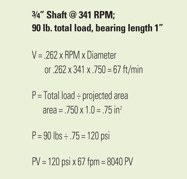
Measuring Operating PV
PV is a means of measuring the performance capabilities of bearings. P is expressed as pressure or pounds per square inch on the projected bearing area. V is the velocity in feet per minute of the wear surface.
For sleeve bearings the surface speed V is .262 x RPM x diameter in inches.
P is equal to the load on the bearing in pounds divided by the projected area in square inches.
For sleeve bearings the projected area is the length times the diameter of the bearing.
PV is then obtained by multiplying the P x V as shown in the following example:
Mechanical Properties
The CJ bearing has withstood static loads in excess of 50,000 psi (345 MPa) at room temperature. However, we do not generally recommend static loads in excess of 35,000 psi (241 MPa). At the recommended load limits, minimal crushing will occur. As the temperature increases, the load capacity of the bearing decreases.
The composite backing tends to act as a shock absorber and reduces vibration. The maximum speed is 150 surface feet per minute for dry running applications.
Corrosion Resistance
The CJ bearing is not affected by corrosive environments. Some solutions of highly concentrated acids will attack the backing material. Specific information can be obtained from our Technical Service Department. The shaft should be stainless steel or chrome-plated if an alloy steel is used. The CJ bearing cannot rust, but when using a lubricant, it should contain a rust inhibitor to protect the shaft.
Read about Bearing Installation Guide (CJ/FCJ Series).


