Accueil >> Étanchéité >>Joints Toriques >> Causes de défaillance du joint torique
Causes de défaillance du joint torique
Comme tout dispositif dont la conception est soumise au jugement, ou dont la pose est soumise à l’erreur humaine, les joints toriques sont sujets à des défaillances. Voici un résumé des modèles de défaillance des joints toriques visant à donner un aperçu au concepteur ou à l’ingénieur des types de défaillances les plus courants, ainsi qu’une liste des mesures correctives recommandées. Il existe de nombreux types de défaillances de joints, et les causes sont multiples. Nous avons donc essayé ici de traiter uniquement les types de défaillance les plus fréquents.
Causes de défaillance d’un joint torique
L’interruption du fonctionnement d’un joint torique est en général attribuable à plusieurs raisons. Le plus souvent, si l’un des problèmes existant au moment de la défaillance n’était pas apparu, le joint torique aurait continué à fonctionner. Il est important de prolonger au maximum la durée et la fiabilité de l’étanchéité en réduisant dès le départ la probabilité de défaillance du joint en utilisant des pratiques de conception appropriées, une sélection de composés adaptée, en effectuant des essais préalables à la production et en donnant une formation et un perfectionnement continus au personnel d’assemblage.
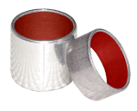
Extrusion et grignotage
L’extrusion et le grignotage du joint torique constituent une cause principale de défaillance des joints dans les applications dynamiques, comme les joints de tige hydraulique et les joints de
piston. On trouve également ce type de défaillance de temps à autre dans les applications statiques soumises à une pulsation de pression élevée entraînant l’augmentation et la réduction du jeu des brides de contact, emprisonnant le joint torique entre les surfaces de contact.
Analyse des défaillances
En règle générale, l’EXTRUSION et le GRIGNOTAGE sont attribuables à l’une des situations suivantes, au moins:
- Jeux excessifs
- Pression élevée (supérieure à la pression de calcul du système ou aux excursions de pression élevée)
- Matériau du joint torique trop souple
- Dégradation (gonflement, ramollissement, rétrécissement, fissure, etc.) du matériau du joint torique par le fluide du système
- Jeux irréguliers attribuables à l’excentricité
- Augmentation des jeux en raison de la pression excessive du système
- Usinage inapproprié de la gorge du joint torique (bords tranchants)
- Taille inappropriée du joint torique posé (trop grand) entraînant un remplissage excessif de la rainure
Voici des suggestions de solutions aux problèmes d’extrusion et de grignotage susmentionnés:
- Réduire le jeu en réduisant les tolérances d’usinage
- Utiliser des bagues antiextrusion
- S’assurer que le matériau du joint torique est compatible avec le fluide du système
- Augmenter la rigidité des composants métalliques
- Remplacer le joint torique actuel par un joint torique plus dur
- Réduire les bords tranchants de la gorge à un rayon minimal de 0,002 po
- Garantir la pose de joints toriques de taille appropriée
Détection d’une défaillance liée à l’extrusion
Les bords du joint sur le côté basse pression (du côté de la gorge où la pression ne s’exerce pas) ont l’air « rognés » ou « effrités » constituent un exemple type d’extrusion du joint torique.
Sur un joint torique défaillant en raison du grignotage, on peut avoir l’impression que de nombreux petits morceaux ont été retirés du côté basse pression. Dans certains cas d’extrusion, plus de la moitié du joint torique peut être détruite avant que l’on détecte une fuite catastrophique.
Compression Set
Probably the most common cause of O-ring failure is compression set. An effective O-ring seal requires a continuous “seal line” between the sealed surfaces. The establishment of this “seal line” is a function of gland design and seal cross-section which determines the correct amount of squeeze (compression) on the O-ring to maintain seal integrity without excessive deformation of the seal element. There are a number of factors that can contribute to compression set failure of an O-ring seal. They are listed below.
Failure Analysis
In general, COMPRESSION SET is caused by one or more of the following conditions:
- Selection of O-ring material with inherently poor compression set properties.
- Improper gland design.
- Excessive temperature developed causing the O-ring to harden and lose its elastic properties.
- Volume swell of the O-ring due to system fluid.
- Excessive squeeze due to over tightening of adjustable glands.
- Incomplete curing (vulcanization) of O-ring material during production.
- Introduction of fluid incompatible with O-ring material.
Suggested solutions to the causes of compression set are:
- Use “LOW-SET” O-ring material whenever possible.
- Select O-ring material compatible with intended service conditions.
- Reduce system operating temperature.
- Check frictional heat build-up at seal interface and reduce if excessive.
Inspect incoming O-ring shipments for correct physical properties.
Identification of Compression Set Failure
A typical example of classic O-ring compression set in simplistic terms: the O-ring ceases to be “O” shaped and is permanently deformed into a flat sided oval, the flat sides of which were the original seal interface and under compression before failure.
Spiral Failure
Spiral failure of an O-ring is often found on long stroke hydraulic piston seals and to a lesser degree on rod seals. This type of O-ring failure is caused when the seal becomes “hung-up’’ at one point on its diameter (against the cylinder wall) and slides and rolls at the same time. The resultant twisting of the O-ring as the sealed device is cycled finally causes the seal to develop a series of deep spiral cuts (usually at a 45° angle) on the surface of the seal.
Failure Analysis
As stated above, spiral failure is generally caused by an O-ring both sliding and rolling at the same time. Conditions which may cause this to occur are:
- Eccentric components.
- Wide clearance combined with side loads.
- Uneven surface finishes.
- Inadequate or improper lubrication.
- O-ring too soft.
- Stroke speed (usually too slow).
- Improper installation (O-ring pinched or rolled).
Suggested solutions to the causes of spiral failure are as follows:
- Improve surface finish of sealed assembly at dynamic interface (Cylinder Bore, Piston Rod).
- Check for out-of-round components (Cylinder Bores especially).
- Provide proper lubrication.
- Replace with a harder O-ring.
- Consider use of alternate seal shapes
Identification Of Spiral Failure
You will see the typical cuts that gave this type of O-ring failure its name.
Explosive Decompression
With the advent of the space age we are seeing this type of O-ring failure with increasing frequency. It might be termed O-ring embolism, in that after a period of service under high pressure gas, when the pressure is reduced too rapidly, the gas trapped within the internal structure of the O-ring expands rapidly, causing small ruptures or pitting on the O-ring surface.
Failure Analysis
Explosive decompression, or gas expansion rupture is caused by high pressure gas trapped within the internal structure of the elastomeric seal element. Rapid decrease in system pressure causes the trapped gas to expand to match the external pressure and this expansion causes blisters and ruptures on the seal surface. If the volume of trapped gas is small, the blisters may recede as the pressure is equalized with little effect on seal integrity. Excessive trapped gas may cause total destruction of the seal.
Suggested solutions to explosive decompression are:
- Increase decompression time to allow trapped gas to work out of seal material.
- Choose a seal material with good resistance to explosive decompression.
- If problem persists and pressures are very high consider use of metallic ‘O’ Ring or ‘C’ Ring.
Identification Of Explosive Decompression Failure
The seal subjected to explosive decompression will often exhibit small pits or blisters on its surface. In severe cases, examination of the internal structure of the O-ring will reveal other splits and fissures.
Abrasion
Another rather common type of O-ring failure is abrasion. This usually is found only in dynamic seals subject either to reciprocating, oscillating, or rotary motion. Possible causes of O-ring abrasion are listed below.
Failure Analysis
In general, abrasion of O-ring seals is caused by one or more of the following:
- Improper finish of the surface in dynamic contact with the O-ring. This surface finish may be too rough, acting as an abrasive, or too smooth, causing inadequate lubrication due to inability of surface to hold lubricant.
- Improper lubrication provided by system fluid.
- Excessive temperatures.
- Contamination of system fluid by abrasive particles.
Suggested solutions to problems caused by abrasion are:
- Use proper surface finish.
- Provide adequate lubrication by use of proper system fluid.
- Consider use of internally lubricated O-rings to reduce friction and wear.
- Check for contamination of fluid and eliminate source. Install filters if necessary.
- Consider changing to an O-ring material with improved abrasion resistance.
Identification Of Abrasion Failure
The O-ring that has failed due to wear through abrasion usually exhibits a flat area on the side of the seal which was in contact with the dynamic surface. Frequently there will be wear lines on this flat surface parallel to the direction of motion. Abrasion failure may be differentiated from compression set failure in that with abrasion, only one side of the O-ring will be flat or worn while with compression set failure, both sides of the O-ring are equally deformed.
Installation Damage
Many O-ring failures can be directly attributed to improper installation. In spite of its simple appearance, the O-ring is a precision device requiring care during installation. Some of the more frequent causes of O-ring failure due to careless handling are listed below.
Failure Analysis
Damage to an O-ring during installation can occur when:
- There are sharp corners on mating metal components such as the O-ring gland or threads over which the O-ring must pass during assembly.
- Insufficient lead-in chamfer.
- Blind grooves in multi-port valves.
- Oversize O-ring on piston seal application.
- Under size O-ring on rod application.
- O-ring twisted/pinched during installation.
- O-ring not properly lubricated before installation.
- O-ring dirty upon installation.
- O-ring gland and/or other surfaces over which O-ring must pass during assembly contaminated with metal particles.
- General carelessness.
Probably the best way to prevent damage to O-rings during installation is the use of good common sense. There are some specific solutions which are listed below:
- Break all sharp edges on metal components.
- Provide a 20 degree lead-in chamfer.
- Check all components for cleanliness before installation.
- Tape all threads over which the O-ring will pass.
- Use an O-ring lubricant.
- Double check O-ring to insure correct size and material.
- Be CAREFUL.
Identification Of Installation Failure
It is difficult to properly illustrate the many possible results of installation failure. One of the more common failure modes is the “Skiving’’ of the O-ring surface due to cutting by metal components. Those cuts are usually very clean as if made with a very sharp knife. Another indication of bad installation will be small cuts or notches on the O-ring. In almost all cases, the damage will appear on the surface of the O-ring away from the bottom of the O-ring groove.
Other Causes of O-Ring Failure
Although not illustrated here, there are several other possible causes of O-ring failure. They are:
- Weather and ozone degradation.
- Heat aging and oxidation.
- Loss of plasticizer.