Home >> Shaft Seals >> Oil Seals >> Design of the Shaft
Design of the Shaft
Ressources techniques
- Le joints d’étanchéité Catalogue en ligne
- Construction de joints d’étanchéité
- Matériau de l’élément d’étanchéité de propriétés
- Sélecteur de compatibilité avec les fluides
- La tolérance de joints d’étanchéité
- Conception de l’arbre
- Conception d’alésage
- L’installation du joints d’étanchéité
- Échange de joint d’arbre (national et SKF / CR)
- Glossaire de termes du joints d’étanchéité
- Feuille de conception de joints d’étanchéité
The Design of the Shaft
Proper application design assures proper sealing performance. Using the following guide will ensure the best possible sealing environment.
Shaft Material and Finish
Seals perform best on medium to high carbon steel (SAE 1035, 1045) or stainless steel. The shaft must be hardened to Rockwell C45 minimum. We recommend the shaft to be machined to a surface roughness of 0.20 to 0.8 µm Ra (8 to 32 µin Ra). This shaft finish can be best obtained by plunge grinding.
Shaft Tolerance in Inches
| Nominal Shaft Diameter | Tolerance |
|---|---|
| up to 4.000 | +/- 0.003 |
| 4.000 to 6.000 | +/- 0.004 |
| 6.000 to 10.000 | +/- 0.005 |
| over 10.000 | +/- 0.006 |
Shaft Tolerance in Metric
| Nominal Shaft Diameter | Tolerance |
|---|---|
| 0 to 3 | + 0.000 / -0.060 |
| 3 to 6 | + 0.000 / -0.075 |
| 6 to 10 | + 0.000 / -0.090 |
| 10 to 18 | + 0.000 / -0.110 |
| 18 to 30 | + 0.000 / -0.130 |
| 30 to 50 | + 0.000 / -0.160 |
| 50 to 80 | + 0.000 / -0.190 |
| 80 to 120 | + 0.000 / -0.220 |
| 120 to 180 | + 0.000 / -0.250 |
| 180 to 250 | + 0.000 / -0.290 |
| 250 to 315 | + 0.000 / -0.320 |
| 315 to 400 | + 0.000 / -0.360 |
| 400 to 500 | + 0.000 / -0.400 |
Shaft Lead-in Chamfer
The end of the shaft must be chamfered, corners must be rounded, free from burrs and sharp edges to protect seals from damage during assembly.
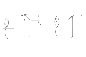
| Shaft Diameter (inches) | C (inches) | R (inches) | D |
|---|---|---|---|
| up to 1.182 | 0.060 | 0.177 | 15º |
| 1.183 to 3.151 | 0.079 | 0.177 | 15º |
| 3.152 to 4.726 | 0.098 | 0.236 | 15º |
| 4.727 to 9.846 | 0.118 | 0.236 | 15º |
| 9.847 to 19.693 | 0.197 | 0.374 | 15º |
| Shaft Diameter (mm) | C (mm) | R (mm) | D |
|---|---|---|---|
| up to 30.0 | 1.5 | 4.5 | 15º |
| 30.1 to 80.0 | 2.0 | 4.5 | 15º |
| 80.1 to 120.0 | 2.5 | 6.0 | 15º |
| 120.1 to 250.0 | 3 | 6.0 | 15º |
| 250.1 to 500.0 | 5 | 9.5 | 15º |
Shaft Eccentricity
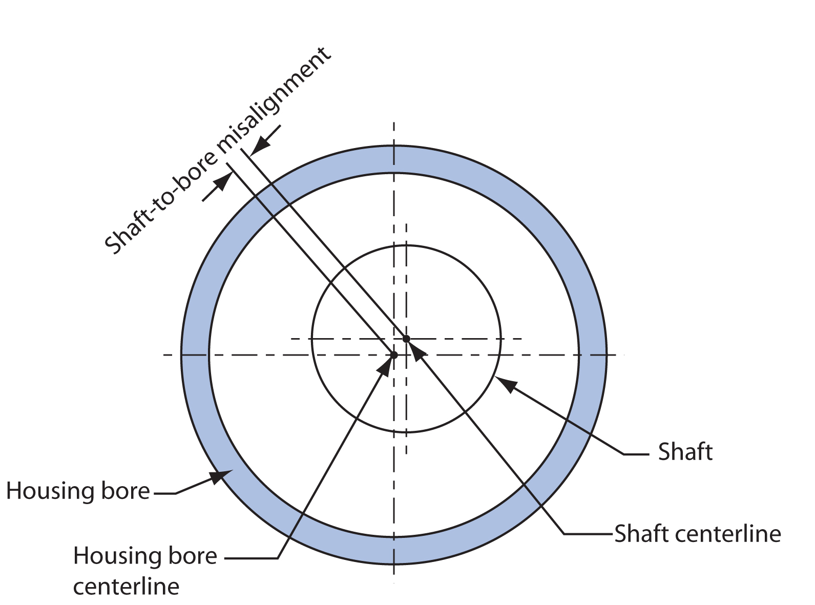
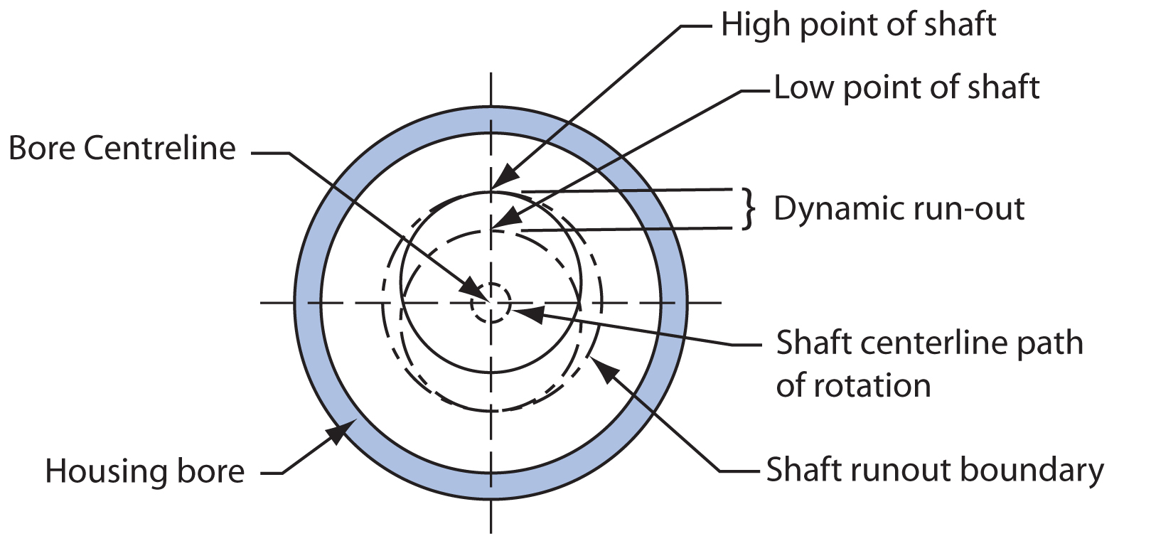
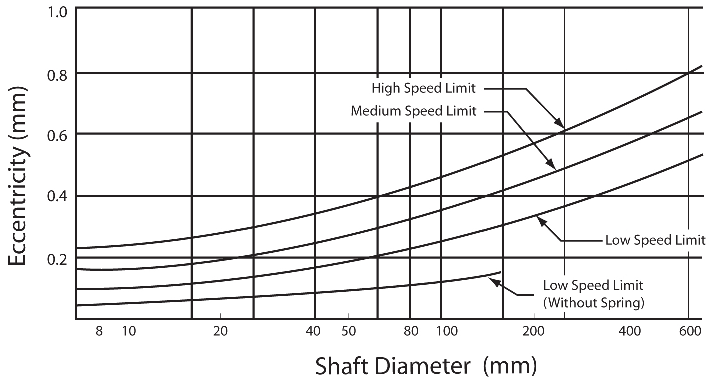
There are two types of shaft eccentricities that affect the seal’s performance. They are Shaft to Bore Misalignment and Dynamic Run-Out.
Shaft-to-Bore Misalignment
Shaft-to-bore misalignment is the distance that the centre of shaft rotation is from the centre of the bore. This situation causes excess sealing lip wear, and poor
contact between the lip and shaft on the opposite side
Dynamic Run-Out
Dynamic run-out is twice the distance the centre of shaft is displaced from the actual centre of rotation. Meaning that the shaft is not rotating around its
centre, causing the lip to flex in and out in order to maintain shaft contact.
In the extreme the lip will not be able to provide the required seal.


