Home >> Slide >> Dryslide Bushings >> Bushing PV Calculations
PV Calculations
The load factor PV has considerable influence on determining the bearings useful operating life. PV is determined by multiplying the specific bearing load or pressure(p) by the sliding speed (v). Bearing materials are rated by a PV limit, with the PV limit representing the highest combination of load and speed under which the bearing material will operate. The PV unit of measure is N/mm² x m/s.
To determine P in an application: the specific bearing load (P) is determined by dividing the bearing load by the pressure supporting are of the bearing. The units for P are N/mm². The pressure supporting area depends on the specific geometry of the bearing, the following are formula for the most common types of bearing geometry.

CALCULATION OF THE USEFUL LIFE
The operating life of a dry application TH sliding bushing is inversely
proportional to the load factor (p x v) but, in order to achieve a
close approximation of the figure, the following corrective factors
must be introduced:
• Ka = constant relative to the type of application
• fp = load correction factor
• fc = application characteristics and temperature correction factor
• fd= bearing size correction factor
• fm = shaft material correction factor


APPLICATION
Having calculated the life of the bushing (Lh), the engineer has to
decide whether to accept or reject the data obtained. If the estimated
life is not acceptable, the sizes of the bushing are modified and a new
check is made following the sequence previously adopted.
For a more detailed estimation of the operating life of DMR bushings
and other products in the series, please complete the Application
Data Sheet at the back of the catalogue and fax it to your local
Daemar Technical Sales Representative.
For applications that come close to the design limits, it is always
advisable to carry out prototype testing.
RUNNING-IN PERIOD
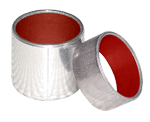
In order to complete the information and the calculations concerning the operating life of the bearings, consideration must be given to the operating method and the degree of wear on the bearings. The bearings have an initial running-in period during which the outer layer of the sliding surface is transferred onto the matting surface, compensating for the non-flatness of the contact and making the coefficient of friction stable.
After the running-in phase, the porous bronze layer is gradually exposed. The surface of the exposed bronze increases with the number of operating hours until it reaches 90% of the contact surface. At this point , the bearing is considered to have reached the end of its useful life.
If, after the running-in period, the bronze is exposed regularly over all the contact area, if confirms that the application was correct.