Home >> Blog >> Technical Considerations for the Selection of Retaining Rings
Technical Considerations for the Selection of Retaining Rings
Design engineers are challenged daily to come up with economical designs that reduce weight, size, raw materials, and labor. This competitive mandate affects every facet of the design, including the fasteners needed to hold components in place. One style of non-threaded fastener that has been widely used to accomplish these goals is the retaining ring. Knowing which ring to use in a given fastening situation can greatly contribute to the overall effectiveness and economy of a design.
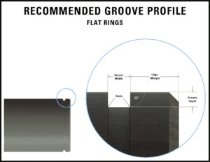
Just as a screw needs a correctly tapped hole, retaining rings need properly cut grooves for best performance. Both groove walls should be parallel and perpendicular to the axis of the shaft or housing.
Groove depth should be held to specifications because the depth and the groove bottom radii determine the amount of support the load bearing groove wall will provide. The edge margin–which is the distance of the groove from the end of the shaft or housing–has been calculated to provide sufficient material to resist shearing even under maximum loads (See Figure 1). Since rings most often fail due to deflection, design examples are given to show how conditions affect capacity thrust.
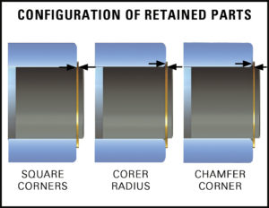
In the first assembly (See Figure 2), the part has sharp corners which provide ideal contact with the protruding portion of the ring and, therefore, the best load support. The other two–one with a radius and one with a chamfer–represent conditions that compromise thrust capacity. You will notice that the retained part contacts the ring at its outer edge. When a load is applied, it creates a lever action against the loaded groove wall. Under extreme loads, this can lead to deflection of the ring and ultimately to failure. If these conditions exist-and this should be carefully investigated before the design is completed—it may be advisable to consider using a reinforced retaining ring to ensure the integrity of the application.
BASIC VS. INVERTED
Equally important to correct groove preparation is the selection of ring types best suited for specific loading conditions. While many ring styles share common design characteristics, each has its own special features which must be considered in relation to the individual design.
For instance, where loading conditions call for maximum groove engagement, basic rings–shown in the left half of each drawing in Figure 3–will be the best choice. However, where load isn’t critical but, let us say, the lug protrusion of the basic rings creates an interference problem–or where a uniformly protruding higher shoulder is of importance–preference should be given to the inverted rings shown in the right halves of each drawing. It is common for inverted ring designs to be used in low load capacity applications where aesthetics are the main concern. The two styles are interchangeable as far as groove dimensions are concerned.

BASIC VS. HEAVY DUTY
In cases of very heavy loads, the reinforced ring, shown at the right half of Figure 4, will out-perform the basic ring because of its greater section height, lug shape and thickness. These rings may also remedy instances of fatigue failure.
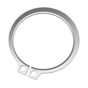
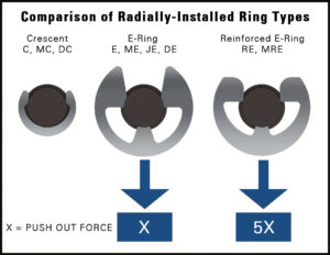
Radially installed rings also differ. The Crescent (“C”) ring at the left in Figure 5 is preferred where space is at a premium and loads are not very heavy. (They are also more tamper resistant).
The E-ring in the middle is ideal for large shoulders, whereas the reinforced E-ring at the right functions best for applications characterized by high vibration, RPM and cyclic loads.
The reinforced ring is interchangeable with the E-ring but grips the groove bottom with 3-5 times the radial force and has greater resistance to fatigue failure. In most cases, its outside diameter/ shoulder is larger than the E-ring’s, which is another factor to consider. All three styles are available in taped cartridges for assembly with dispensers and applicators.

BOWED RINGS FOR RESILIENT ENDPLAY TAKE-UP
Retaining rings can also be used to compensate for accumulated tolerances or wear in the assembly, and also to exert pressure against the retained parts. Most retaining rings are made from spring materials and are heat-treated to retain their resiliency. The bowed rings (Figure 6) can be flattened under pressure and will return to their set height when pressure is released. It follows then that when the ring is flattened either partially or completely, it exerts counter-pressure in much the same way as a spring, taking up endplay.
In the two illustrations at the left in Figure 6, compression is minimal, whereas on the right both rings are flatter. The flatter rings indicate that the retained parts were slightly longer and the rings adjusted themselves to this condition. Because of their resiliency, bowed rings will “follow” any axial movement of the retained part within the limitations of the bow height. However, precision loading is not the only design goal for their use. Bowed rings produce a compressive force to reduce chatter and vibration.
There are also retaining rings that combine the features of radial installation with endplay take-up. In Figure 7 the ring is a basic E-type, bowed over what is shown here as its horizontal axis. It can be pushed into the groove from the side of the shaft and will exert axial pressure against the retained part.


BEVELED RINGS FOR RIGID ENDPLAY TAKE-UP
Beveled rings serve essentially the same purpose but they work on a different principle. Advantage is taken of the ring’s spring characteristics, but in the ring’s own plane. The internal ring has a 15 degree bevel along the outer periphery, the external ring along the inner edge. The groove profile corresponds to that of the ring, with the beveled wall bearing the load. Here, too, the calculation of groove location is of utmost importance.
The drawings at left, top and bottom of Figure 8 show minimum groove engagement; that is, with the ring seated to at least half the groove depth. The internal ring is compressed to less than its free diameter, whereas the external ring is spread more than its free diameter. The spring properties of the rings will cause the internal type to open and the external type to close more completely, in each case exerting axial pressure against the retained part.
The groove location must be precise to prevent full bottoming of the ring in the groove. The ring acts as a wedge between the groove wall and the part, which it locks rigidly. The assembly will not “breathe” as with a bowed ring that may deflect under load.
While the beveled edge of the ring moves along the beveled groove wall for further endplay take-up, until it may conceivably reach the position shown for maximum groove engagement, it cannot back out, even under load.
It is important to note that bowed rings offer greater endplay take-up than beveled retainers. However, beveled retainers offer rigid endplay take-up and should be considered where cyclic loads occur. (High rotational speeds do not work well with beveled retainers.

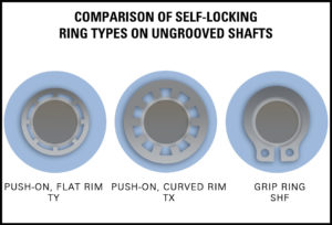
SELF-LOCKING RINGS ON UNGROOVED SHAFTS
Self-locking retaining rings are used on shafts without grooves. The simple circular ring at the upper left of Figure 9 has a flat rim and will support moderate static loads.
It is used widely because of its relatively small outside diameter.The reinforced circular self-locking ring next to it has a curved rim and will handle greater loads even if some vibration is present. However, it has a larger outside diameter. These two rings work on the same principle: the prongs resist counter-pressure by digging lightly into the shaft. The fasteners can be moved, therefore, in one direction only. They should be used on non-hardened/soft shafts and, in most cases, must be destroyed to be removed.
In this respect, the grip ring shown at the lower right has an outstanding advantage. It can be moved in either direction and its position adjusted after installation by using retaining ring pliers that fit into the lug holes. It can be used over and over again. These characteristics make it more suitable for applications where components may have to be disassembled for repair or maintenance.
Whatever the fastener requirement, you can find a retaining ring that can meet it. The challenge is to find the right one that will perform according to your specifications and deliver the expected economies. Considering the rings described above is a solid first step to achieving that objective.
To learn about selecting the correct products for your operating environment please contact your local Daemar Technical Sales Representative.