
Home >> Shaft Seals >> DMR Bearing Isolators >> DMR Protech Installation Instructions
DMR Protech Installation Instructions
Protech Bearing Isolator instructions.
Standard Design Installation
The Protech seal is unitized; any attempt to dissemble the seal will damage it. After making any adjustments to the equipment, confirm that the seal is still properly installed.
Prior to Installation
1. Warning! Disconnect all system power, and follow all standard safety procedures.
2. Remove all sharp edges from the following:
a. Lead-in chamfers
b. Keyway
c. Splines
d. Snap ring grooves
3. Clean all foreign debris from bore and shaft areas.
Installation
1. Lubricate bore and shaft O-rings with systemcompatible lubricant.
2. Position the seal over the shaft by hand. Seal position is correct if the stator O-ring is towards the seal housing as shown.
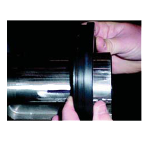
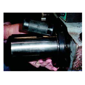
3. Slide seal down the shaft, stopping just before the seal housing of the equipment. Use hand pressure only.
4. Rotate the seal so that the drain port is centered at the six o’clock position.Press seal into bore using hand pressure only. If necessary, gently tap seal into bore using a soft faced
tool.
DO NOT USE A METALLIC HAMMER OR PUNCH as this may damage the seal.
Split Seal Installation
Prior to Installation
1. Warning! Disconnect all system power and follow all standard safety procedures.
2. Remove sharp edges on the shaft and bore where the seal will be installed. Make sure there are proper lead-in edges.
3. Clean all foreign debris from the bore and shaft area.
Installation
1. Pre-lubricate the O-rings with a system compatible lubricant.
2. Position the shorter O-ring on the shaft and place the two halves of the rotor, with the flange sides facing away from the bore, over the O-ring so the O-ring fits into the groove (see Fig. 8-2). (It might help to first paste the O-ring to the shaft with a light coat of grease.) Then place the screws in the rotor halves and screw the two halves together loosely. Do not tighten the screws.
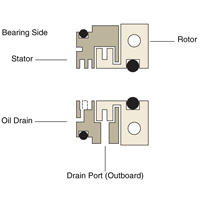
Figure 8-2 Position the Rotor Halves
3. Place the two halves of the stator over the rotor at the bore side so they interlock with the rotor. Rotate the stator until the drain port is at the six o’clock position. While holding the parts together by hand, wrap the long O-ring into the stator O-ring groove with the ends of the O-ring meeting at the 12 o’clock position. Gently slide the seal into the bore while keeping the O-ring in the groove (see Fig. 8-3).
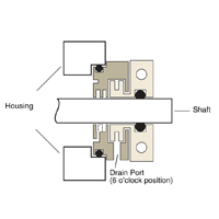
Figure 8-3. Proper Installation
4. Gently tighten the screws; stopping a few times to make sure that the shaft can turn freely. Tighten the screws so the halves of the rotor meet. Do not turn the screws more than one eighth turn beyond where the halves meet.
DO NOT OVER-TIGHTEN THE SCREWS. After making any adjustments to the equipment, confirm that the seal is still properly installed.


