Home >> Blog >> Calculating Endplay Take-up for Beveled Rings
Calculating Endplay Take-up for Beveled Rings
In many manufacturing assembly lines, dimensional tolerances in ring thickness, groove location or the overall length of the components being retained add up to a degree of clearance, or endplay between the abutting surfaces of the ring and retained part. In some cases, the endplay can be eliminated by shims, washers and similar devices or by “selective assembly” in which parts with plus or minus tolerances are matched carefully to provide the desired tight fit. But in high speed production these alternatives can be prohibitively expensive both for materials and assembly labor.
Manufacturers have benefitted from substituting beveled retaining rings for these other alternatives. Beveled rings provide all of the cost savings benefits of conventional rings with an added advantage: they compensate for accumulated tolerances or wear in the retained parts and provide rigid endplay take-up in the assembly. This permits manufacturers to work with larger tolerances in the parts being assembled and still achieve required performance characteristics.
Design Features: Rigid Endplay Take-Up
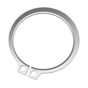
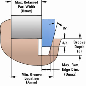
Beveled retaining rings are similar in construction to the standard internal and external types. They differ from the standard rings in that the groove-engaging edge is beveled to a 15° angle. (The bevel is located around the outer circumference of the internal rings, around the inner
circumference of the external rings.)
The rings are designed to be used in grooves having a corresponding 15° bevel on the load- bearing groove wall. The ring should be seated at least halfway down into the groove to provide sufficient contact area with the load-bearing groove wall.
When a beveled ring is installed in its groove, it acts as a wedge between the outer groove wall and the part being retained. When there is endplay between the ring and the abutting face of the retained part the ring‟s spring action causes the fastener to seat more deeply in the groove,
compensating for the endplay.
Beveled grooves differ from standard ring grooves in two important respects. As indicated previously, they have a 15° angle on the outer wall of the groove and they are considerably deeper than standard ring grooves. The beveled wall matching the beveled edge of the ring is necessary for maximum ring effectiveness. The groove loads listed in the manufacturer‟s data charts are based upon minimum ring engagement; i.e., with the ring seated halfway into the groove. For this reason, the groove loads are somewhat less than the maximum loads for equivalent sizes of flat rings.
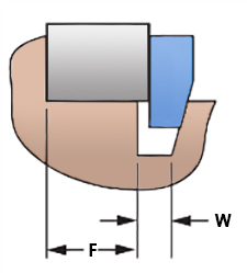
If the “A” dimension is maintained and the cut is made accurately from the fixed shoulder to where the beveled portion of the groove intersects the housing or shaft diameter, the listed plus tolerance for groove width “W” may be held or increased as required. If the beveled edge of the groove is located by establishing the “A” dimension from the fixed shoulder to the straight wall of the groove, the listed plus tolerance for “W‟ must be reduced (See Fig. 1C) and will be referred to as the “F” dimension (Fig.2). (Note: It is not recommended to locate a groove using the “F” dimension as it introduces extraneous tolerances.)
In order to determine if a beveled ring will be functional in an assembly, a comparison must be made between the total tolerance of the assembly and the capability of the ring to fulfill this requirement. This fulfillment is achieved when the ring seats anywhere between halfway down to all the way down in the groove depending on the tolerance build up in a particular assembly. This is shown in Figures 1A and lB and may be expressed as follows:
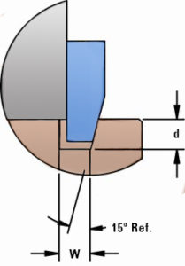
Ring Take-up= d/2 tan 15° ≥ ∆A + ∆B + ∆U

(Near Groove Bottom)
Calculation of Groove Location and Analysis of End-Play Take-Up
The recommended procedure for calculating the groove location is
A¹ ≥ B max+ U max+ d/2 tan 15°
A² ≤ B min+ U min+ d tan 15°
Inspection of Ring Beveled Edge
(“U” Dimension)
As is noted on the manufacturer’s data sheets for both internal and external beveled rings, the beveled edge width, designated as the “U‟ dimension should only be used for calculating the groove location and take-up requirement as was illustrated in the previous section. No attempt should be made to directly measure this dimension since the point at which the measurement should be taken is not clearly defined due to the blanking crown and die clearance taper on the ring edge. During the manufacture of these rings, techniques other than the direct measurement of this dimension are utilized to be sure that the dimensional integrity of the parts has been maintained.
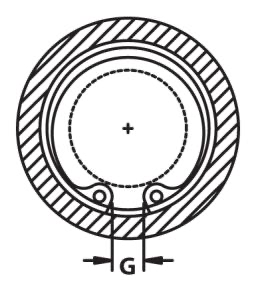
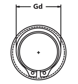
Checking Ring Installation: Dimensions “G” and “Gd”
As indicated previously, beveled rings must be seated at least halfway in the groove to provide sufficient contact area with the load-bearing groove wall. The dimensions for minimum gap width G (internal rings) and maximum gaging diameter Gd (external rings) provide a quick means to determine if beveled rings are seated at least half way in their grooves. If the gap measured on an installed internal ring is less than the listed dimension, the ring is not seated properly and may fail. If the maximum gaging diameter measured on an installed external ring is greater than the listed dimension, once again the ring is seated improperly and may fail. In either case, the ring should be removed and another installed. If the condition persists, the entire assembly should be checked for excessive tolerances on the retained parts.
Today‟s demands for reduced costs extend to every component of an assembly. Fastening methods that require multiple components like shims and washers should be re-evaluated to determine feasible alternatives. Beveled retaining rings are a clear option paving the way for effective retention with a minimum cost in materials and labor. Following the guidelines above can help you determine if this fastening method is right for your application.
To learn about selecting the correct products for your operating environment please contact your local Daemar Technical Sales Representative.